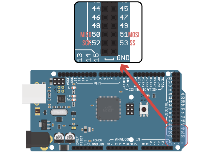

Since the value on pin 10 is ignored, providing it is set as an output, then it can also be used as the SS line for your first, or only, slave. If configured as an output the Arduino ignores the value on that line, and thus the SPI hardware will not be put into slave mode. Pin 10 of the Arduino is the SS line - so does this mean you have to use it for the peripheral SS line? Or should it be kept high? The answer (from the Atmega documentation) is that the SS line (pin 10) must be configured as an output (regardless of what value is on it). Then, and only then, should they configure their MISO line (master in, slave out) to be an output, so they can send data back to the master. Thus, slaves should let each of the lines float (as inputs) unless their slave select is taken low. This way you only need 3 wires (plus ground) in total, plus one slave select for each slave. The way this is done is to tie the SCK, MISO and MISO lines together (for each slave) and have a separate SS (slave select) line for each slave. This is because the SPI hardware can be used to communicate with a number of slaves at once. There is a bit of confusion about the Slave Select pin. The code to produce this (in Arduino's C++ language) was: Also the slave should ignore any clock pulses now (they may be for a different peripheral). At this stage the slave should release the MISO line (configure it as an input, or "high impedance").

Also the slave can place data on the MISO line for the master to simultaneously read in. This tells the slave to read the data on the MOSI line. For each of the 8 bits the SCK (clock) line is briefly brought high, and then low again.

It shows the 3-character sequence "Fab" being sent from the Arduino.

Let's start with an image - this is a screenshot taken with a logic analyser.


 0 kommentar(er)
